I've started a new blog here. This one will stay at this address for the time being but will eventually be archived.
Friday 29 November 2013
Comments closed, migrating away from this platform
By alecjw on Friday 29 November 2013, 20:08
I've disabled comments on this blog, since I got ~5000 spam comments since I last checked it. I also don't really like the markup, so I'll be migrating away from this platform before my next blog post - I may reluctantly end up using wordpress. Watch this space for more info - obviously I'll write a final post here to say where the blog's moving to.
Thursday 27 June 2013
Samsung Customer Service Disaster - A Rant
By alecjw on Thursday 27 June 2013, 18:18
WARNING: This blog post is one long incoherent rant. Read at your own risk.
Recently my Samsung Galaxy Nexus developed a fault: It wasn't detected when plugged in via USB and it wouldn't charge (except very slowly when switched off). I read that this was a common problem and the USB port needed to be replaced. Since it was under warranty, rather than spending a fiver and half an hour of my time, I thought I'd exercise my consumer rights by sending it in to Samsung for repair. Bad move, as it turns out.
I phoned up the call centre and soon it was booked in to A-Novo for repair. I posted off my phone in the jiffy bag they provided and the next day, my phone was marked as "Non defect (working properly)" on the website. A few days later I got an invoice for GB£138 to replace a cracked screen. Needless to say, there was nothing wrong with the screen when I sent it in. I had the option of paying this charge, paying an unspecified administrative charge for the phone's safe return without repair, or letting them destroy my phone.
I phoned up A-Novo who said that since the packaging wasn't damaged there was nothing they could do, and that I should contact Samsung instead. I decided this was a job for another day. Then the next day, they returned my phone without any warning. I put the battery in, switched it on and found that there was still no damage to the screen. By Hanlon's razor, I'll attribute this to crass stupidity rather than intentional deceit. Anyway, I phoned up customer service again. The person on the phone apologised and, after putting me on hold to talk to her manager, booked my phone in to another service center (Regenersis).
After I sent my phone into regenersis, they returned it fixed within two days, yay! Unfortunately, they also unlocked the bootloader (which tends to void one's warranty) and reflashed it with the wrong software - I sent it in with android 4.2.2 and they sent it back with 4.1.1. At this point I decided to cut my losses and reflash it myself rather than sending it back in. So I now have a working phone again, but not without a huge amount of stress and hassle.
I used the "Email the CEO" feature on Samsung's website to complain about my experience, but all I got back was an email from (presumably) some customer service rep containing the usual "we're sorry to hear this" platitudes. Overall, I wasted a lot of time dealing with Samsung over this. Would not recommend.
Monday 27 May 2013
Stinkpipes and Sewers of Cambridge
By alecjw on Monday 27 May 2013, 20:49
A while back, I spotted a mystery object near where I lived. Here it is
below, the location is 51.772587,-0.202331: 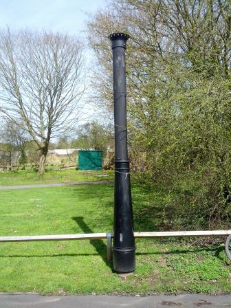 (More pictures here)
I asked around for identification and eventually a friend of mine told me it was a stinkpipe. But what is a stinkpipe? To quote Teakay, "Stinkpipes (or stenchpipes) are the overground remnants of a Victorian invention to vent stink from inefficient sewer systems so that it could skip the bit of airspace that contained people's nostrils."
Since spotting this, I've been keeping my eye out for stinkpipes elsewhere. And just recently, I've noticed a few in Cambridge. While the weather was nice today, I decided to go out stinkpipe spotting.
I started at Homerton College (my home) and noticed there were a few in the
small roads just off Hills Road. The southernmost one I found was on Cavendish
Avenue. Its base had no manufacturer's markings: 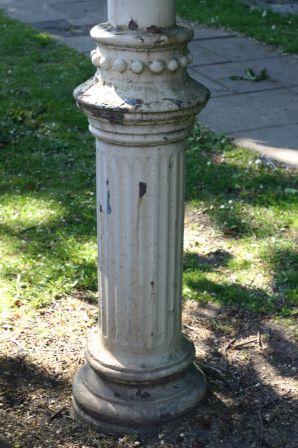 And the top was lost in the trees, but still had its distinctive stinkpipe
crown:
The next one I found, on Marshall Road, was similar; but on Hartington Grove
was one missing its crown: 
After these first three, I cycled around for a bit trying to find where the
sewer went next. Did it cross the railway and continue along Hills Road? Maybe
it took a right onto Cherry Hinton Road. I went a short way down CH road
without finding any stinkpipes, so I turned around and came back. But on the
way back, I found this one, sneakily hidden behind a telegraph pole so I didn't
see it coming from the other direction. 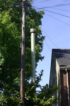
I figured the sewer must continue up Rustat Road from here, and it turns out
I was right. The stinkpipes on this road even had markings on them - Broad
& Co Ltd, London. I googled this to no avail. 
A few pipes later, the clues ran out this side of the railway line beyond
Cromwell Road. I'd previously seen a pipe at Jesus Green, so I figured there
might be some sort of confluence there. Because of this, I hazarded a guess
that the sewer might veer left and cross the railway here. Sure enough, I found
another on Silverwood Close. This one was painted a different colour to the
others, but also had a different marking, John Spencer Ltd, Wednesbury.
 A quick google reveals that John
Spencer existed from 1882-1935, so that gives us some sort of date range
for this sewer's construction.
After this I went back to Jesus Green to photograph a stinkpipe I'd spotted
there previously. This is the only Ham Baker one I've found in Cambridge:
 The bottom's been repainted, but the top is
still in flaking, rusty green.
I did a search of the perimeter of Jesus Green and noticed that there were
another few on the other side of the river. Further to this, I also noticed a
black pipe running across the bridge - perhaps this is a sewage pipe? 
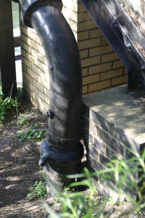
So that's just about it. I haven't listed all of the findings here, just the interesting ones, you can see all of them on this map:
East of the train line you can see there's very clearly a sewer going N-S. Whether it ducks under the train line and re-emerges on Silverwood Close or if that's a separate sewer isn't quite so clear. The trail runs a bit thin from here. There's clearly something running along Chesterton Road, and google tells me that this is the Chesterton to West Cambridge Sewer. Perhaps this crosses the river and there's some sort of confluence under Jesus Green? If anyone has any thoughts, or spots any other stinkpipes in Cambridge, let me know in the comments!
Edit 2014-04-06: Just a quick update - as you can see from the map above, I've found lots more stinkpipes since I wrote this blog post. The pipes seem to form at least 3 lines radiating outwards from the old sewage pumping works. A couple of the stinkpipes I found (nos 35 and 38 on the map) have been cut off just above the base and filled in. For #35 (Thoday Street) it seems to have quite a long shadow in google satellite view, so perhaps this is recent? The Cambridge Historian tells me that the iron railings around Parker's Piece were collected and melted down as part of the war effort, so perhaps that would explain where #38 went.
Saturday 20 April 2013
Mystery Aircraft Parts and Atomic Clocks
By alecjw on Saturday 20 April 2013, 01:18
A couple of weeks back I stumbled across a thing on ebay. The seller
described it as an "Aircraft stable oscillator" but knew nothing more about it.
I was interested for two reasons: firstly, it was made by GEC Marconi - a
predecessor to the company I now work for. And secondly, from the name it
sounded like it might contain an OCXO - which would have been handy to use as a
frequency reference. Anyway, it was £20 delivered so I figured I may as well go
ahead. Here it is: 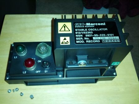
Let's crack it open! Not much to see yet. The main board has some 74HC
series logic, a 7805 linear regulator, a P-channel mosfet and a couple of
2n2222 NPN transistors on it. On the far right you can see a power supply
decoupling board - not sure exactly what the filter topology's called but it
looks like two cascaded pi filters. You can also see marks on the inside of the
case which show that it's been machined. 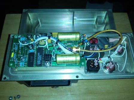
From another angle you can see a thermostatic switch underneath the board.
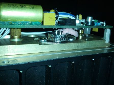
Removing the PCB and thermostat and taking out the mounting posts, I could
then extract this: 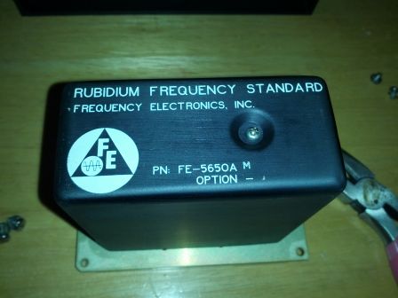
An atomic clock for £20! Excellent! I had a look at the datasheet to find the pinout. Tracing the tracks on the original circuit, it seems that this variant was a single-supply one, needing only +15V (EDIT: actually 19.5-38v, see addendum). Most of the circuit seemed to be dedicated to just switching the green lamp on once the frequency had stabilised (these units take a few minutes to warm up) and the red lamp on otherwise - so nothing particuarly interesting here.
Some variants of these could have their frequency set by RS232 but this
particular model didn't seem to be one. I hooked it up to a bench power supply
and measured the output - an 800kHz square wave. 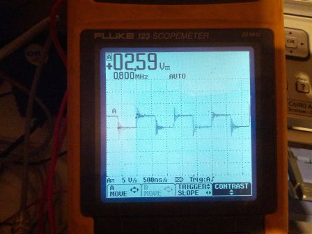
This was slightly annoying - I was hoping for a 10MHz reference for my test
equipment. I wondered how I could change the frequency. Perhaps I could
multiply the output frequency by 25 somehow and divide by 2? Maybe by filtering
out the 5th harmonic of the square wave twice, or using a PLL? The datasheet
hints that these devices can be set to a frequency of your choice out of the
factory, so perhaps i could change the frequency of mine in the same way that
they set them initially? I opened it up and found that all of the interesting
circuits inside were potted with what seemed like some sort of polyurethane
foam. 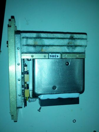
Just as I was running out of ideas - being too afraid of damaging it to try removing the foam - a friend recommended that i try the time-nuts mailing list. I asked on there if anyone knew how to change the frequency of these and was met with a number of very helpful responses! Unfortunately most of the information they had was on the FE-5650A-58 option with the RS232 control but i did extract a number of useful bits of information here. Firstly, all of these devices have a 50.255MHz clock at their core (the big metal can in the picture above!) and mine most likely uses a DDS chip to create the output from that. Also, changing the output frequency isn't quite as easy as just changing the DDS tuning word since they tend to use crystals on the output for filtering.
As an interesting piece of background, i also found out from G8RPI that these oscillators are from a frequency hopping system called HAVE QUICK.
Anyway, with this information i was sufficiently intrigued to risk picking
away at the foam to find out what was going on. 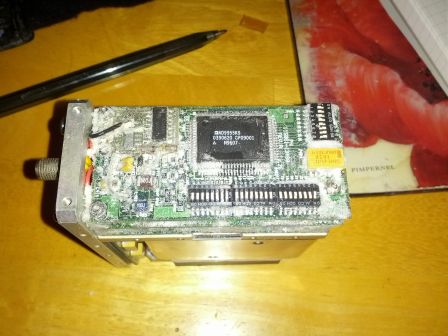 With the majority of the foam
removed I could see the DDS chip - an AD9955. I'm not very
patient when it comes to reading things but the gist i got from skimming the
datasheet was that a signal goes into CLK, a 32-bit word F is input in parallel
and the output frequency is Fin*F/2^32. On this board the 32 DIP switches are
clearly to set F, Another thing I noticed was that the DDS isn't actually set
to 800kHz - at the top left is a 4040B ripple counter, which divided a 12.8MHz
clock down by 16 to produce the output.
I wanted to verify my theory that the AD9955 was dividing down the 50.255MHz clock down to 12.8MHz. Reading the DIP switches (assuming that in to the board=1 and towards the edge=0), the tuning word was set to x4134111F. Dividing this by 2^32 and dividng 12.8MHz by this gives 50.255058MHz... pretty much spot on! From now on I'll take this as the frequency of the reference clock.
So, i now know how to change the DDS divider, but what about the crystal
filter? I figured this must be underneath the board I was looking at, so I
undid the nuts holding it in place and gently pryed it off. (Be careful of the
header and loose wires connecting the boards near the SMA connector end!)
Underneath, sure enough, was a crystal. It seemed to be connected (possibly via
a resistor?) to the COUT pin of the DDS. 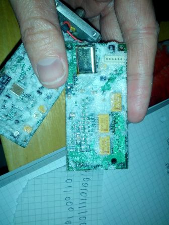 The markings (156/Y-1294-2) didn't
seem to indicate its frequency or manufacturer and googling them didn't help.
Regardless, I desoldered it to unlock the frequency range of the DDS chip.
By some simple maths i calculated the tuning word for 20MHz was x65E15AC0. Why 20MHz? Well, i was going to have to put a crystal back in eventually, but i couldn't find any 10MHz ones in my junk box! I had plenty of 20MHz ones though so i decided to improvise... i'd make a 20MHz clock, then rewire the 4040B counter to divide by 2 rather than 16. This also has the advantage of giving me a CMOS logic buffered output. Anyway, i switched it on and probed it to find my 20MHz signal i was after. It was a bit ugly because of the lack of filtering though.
Here you can see i've bodged in a replacement 20MHz crystal. I've wrapped it in kapton tape and grounded the end, just like the original one. This one was a smaller package though, so I had to scratch away some of the soldermask from the PCB to tie the can to ground.
I fired it up again for a smoke test. 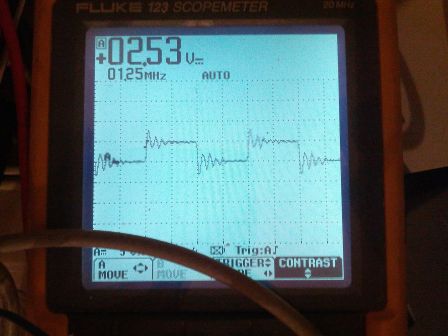 As hoped, i saw a 1.25MHz square wave on the
output - the by-16 divider still in place. Next job was to change the divider
to by-2. This simply involved disconnecting the output from Q4 of the ripple
counter and connecting it to Q1 instead.
 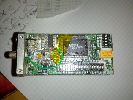 In doing so, I noticed that the
output was decoupled with a 330pF and 100pF capacitor across the SMA connector.
At 10MHz, this amount of capacitance won't do, so i... ripped the capacitors
off with a pair of pliers.
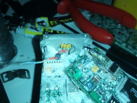
With this done, i put it back together and revelled in my success! 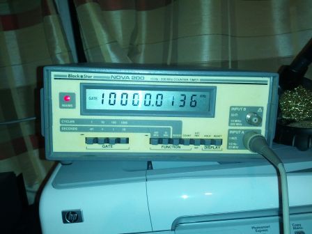 The error in frequency here is
almost certainly due to the innacuracy of the counter (bought for a tenner at a
radio rally) rather than of the source.
Thanks to Herbert Poetzl, Robert G8RPI Atkinson and Bill WB6BNQ - all from time-nuts - for their invaluable advice with these frequency standards! After I found one of these inside the Mysterious Aircraft Part, i decided to buy the seller's remaining stock (another 6 of them) since a rubidium frequency standard must be worth more than £20. I'm now selling them on ebay and I'm considering offering them with 10MHz modifications. Once I've extracted the frequency standards, I'm left with a very nice machined aluminium casing which will make a great project box - it's aluminium with fins so will be good for high power dissipation stuff. Audio amplifier project maybe? The cases also seem to be IP67, with the power switch and connectors rated thus and a rubber gasket around the edge where the two sections come together. Perhaps it's time for an underwater electronics project!
ADDENDUM 1: Input Voltages
Since i wrote this post, Robert G8RPI has pointed out that these units
aren't actually designed for a 15v input voltage! They actually have a
switching pre-regulator on board, as you can see below. 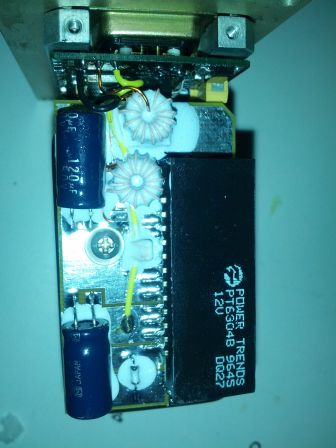 This buck regulator is set with a
91kohm resistor to give a nominal output voltage of 15.3v. I measure it to
actually be nearer 15.5v. With a dropout voltage of 4V, this gives a
permissible input voltage range of 19.5-38v. This is apparently so it could be
used directly from an aircraft's 28v supply. I could have easily removed this
board by undoing the screw, prising off the edge which is potted to the Rb
package, desoldering it from the main power supply board and placing a short
between where the ECW and the yellow wire used to go. I decided to keep it for
now though - it will be quite handy to be able to run this thing from an old
laptop charger!
ADDENDUM 2
So, some people have gotten a bit upset that I bought all of these and am selling them on for more. I appreciate it's frustrating but... hear me out. For £20 I bought a completely undocumented part on a hunch - for all I knew it could have been completely worthless. I took on that risk of losing out. Once I'd found that it was actually worth something, I spent hours of my time dissecting and documenting it here. So I'm now selling on a documented part - you know what's inside it and you don't have that risk of losing out! Also, I have college bills to pay :) Tl;dr: I charge a premium for the elimination of risk and for my time.
I've listed a complete unit on ebay since it seems like some people would be interested in getting hold of the whole thing.
Friday 8 February 2013
A rough and ready hit-counter
By alecjw on Friday 8 February 2013, 14:58
A page on my website has become surprisingly popular recently, and I wanted a dead simple way of tracking hits. I thought I'd share what I came up with in case it's useful to anyone else. My requirements were:
- Track hits on one page only
- Be transparent to the visitor. That is, no annoying javascript or a readout of "you are the nth visitor" on the page itself. I pride myself in the simplicity of my web design.
- Handle the numbers of hits I'm getting at the moment (hundreds or low thousands per day)
- Ideally, track when the page was visited, so I can do some stats on most popular times of day, and change in popularity over time.
Here's my solution. I simply moved index.html to main.html and created an index.cgi:
#!/bin/sh

date +%s >> logfile

echo "Content-Type: text/html"

echo

cat main.html
Simplicity itself.
I also created a hitcount.cgi so I can check just by visiting the page how many hits it's had:
#!/bin/sh

echo "Content-type: text/plain"

echo

wc -l logfile | sed -e 's/ logfile//g'
I will post some MATLAB analysis later on, once I've collected enough data.
In terms of limitations, a friend suggested to me that if two people visit at the same time, the file might end up getting clobbered and having lines mixed up. But at the current rate, two people visiting at once is unlikely; and in any case I can deal with having one anomalous date in my log if this does happen.
Saturday 22 December 2012
On lossy compression...
By alecjw on Saturday 22 December 2012, 21:05
A while back I heard some samples of the difference between lossless files and their compressed forms (MP3) and thought it seemed pretty cool to hear what data the compression algorithms are throwing away. I just got around to trying this for myself. Here's what I did:
- First things first, you'll need sox with the appropriate formats installed. Optionally install octave, and vorbis-tools or a compressor of your choice. On debian: apt-get install octave sox libsox-fmt-all vorbis-tools
- Start with a lossless file, eg a FLAC or a WAV ripped from a CD.
$ sox ~/Music/Dalriada/Jegbonto/05\ -\ Téli\ ének.flac
original.wav
- Convert it to a lossy format. I'd reccomend using vorbis, since I had trouble with MP3, see below. For example:
$ oggenc -q 5 -o lossy.ogg original.wav
- Convert the compressed file and original to RAW format. Check that they're the same size.
$ sox original.wav original.raw

$ sox lossy.ogg lossy.raw

$ ls -l *raw
- Start octave or matlab and run the following commands to subtract the files as 16-bit signed ints (alternative follows):
> original=fread(fopen('original.raw'),Inf,'int16');

> lossy=fread(fopen('lossy.raw'),Inf,'int16');

> fwrite(fopen('out.raw','w'),original-lossy,'int16');
- Alternatively, if you don't have/want to install octave, Techmeology provides some C code to acheive the same thing.
$ gcc -o compare compare.c

$ ./compare original.raw lossy.raw > out.raw
- Now convert it to a usable format (eg wav). Optionally you can amplify it to bring it to an audible volume level. Here I've applied 10dB of gain:
$ sox -r 44100 -t raw -e signed-integer -c 2 -b 16 out.raw out.wav
gain +10
And there you have it. I was left with a sort of haunting ghostly screaming sound. I would share but you know, copyright and all that. If anyone can suggest some creative commons music to publish samples of though, I'd be happy to do that.
I have noticed a problem though - by converting to MP3 and back you seem to end up with fewer samples. I've tried padding it out with zeros before the comparison, but it then the difference file becomes just a choppier-sounding version of the original. If anyone knows how to resolve this, please do let me know.
Sunday 16 December 2012
RPi Server
By alecjw on Sunday 16 December 2012, 14:47
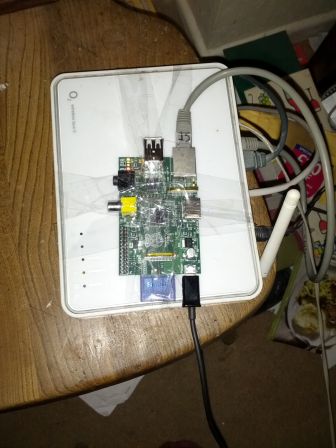
I've tried to set up a home server several times, from old desktop PCs or laptops, or xboxes. But the problem has always been bulk, noise, parental interference and power consumption. Since all i need is a seedbox and perhaps a web server, the RPi seemed ideal. Here's my attempt at making a parentproof home server. It has a 32GB SD card for storage (I think I bought it for £20 at Asda) and It's powered from a phone charger. I've sellotaped it to the top of our router and glued the network cable in place. The only weak point is the power supply, and I'm not sure if there's anything really I can do about that. It's running raspbian and it serves hatfield.m0tei.co.uk
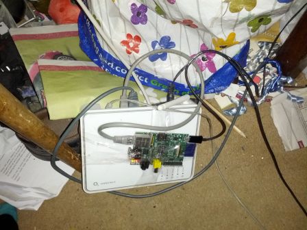
EDIT: Parents accidentally (?) yanking the power cable out has started to become a problem. I've found a solution though:
By the cunning application of sellotape, there's now no direction in which you can yank the cable for it to come out of the RPi before the router comes unplugged. I tried throwing it around a bit and that router power cable won't budge.
Sunday 18 November 2012
Culinary Engineering #2: Chutney
By alecjw on Sunday 18 November 2012, 00:44
Today I made red onion chutney. My method, summarised concisely:
Slice N red onions and cook on the hob at a low heat with a little oil. I
used a lid but I'm not sure if this was nescassary. For me it took about 20-30
minutes before they were soft. 
Add 37.5N millilitres of red wine vinegar and 25N grams of sugar. Leave to boil on a low heat. I left the lid on for about 10 minutes then took it off and turned the heat up, letting it reduce.
Once it was of a chutney* sort of consistency, I considered it done and put it in a jar (cleaned out and sterilised with boiling water), then let it cool. For N=4, I made enough to fill a 450g curry sauce jar.
The finished result, served with cheddar and crackers:  Omnomnom
Edit: I should add, in hindsight I would have cut the onions a bit thinner - it came out a bit coarse.
*I hereby claim "chutney" as an adjective. Chutney, chutnier, chutniest.
Friday 16 November 2012
Reprap Build: Phase 3
By alecjw on Friday 16 November 2012, 17:55
It's been a while since my last update, not for lack of having done anything, but rather because I haven't had much time to write it up.
First things first, the frame has progressed some more, and the lower print
bed is now attached: 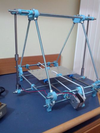
Mostly no problems here, except at the top of the frame I found that the M3
bolts were a bit too long and interfered with the motor, so I put three washers
on each one: 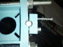
My main achievement recently though is with the heated bed. My first plan
was to take a plate of aluminium and glue the PCBs to it copper-side to the
metal, but first covered with conformal coating to prevent short circuits. I'd
fix them down with superglue round the edge and thermal paste in the middle. I
first drilled a hole through the corners of the PCBs... 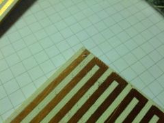 ..and put vias through, soldered on
the track side and sticking out the component side.
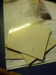
This left raised blobs of solder on the board, so to accomodate for these I
dremelled away at the bottom of the aluminium sheet. 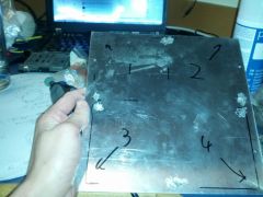
I covered the PCBs in conformal coating, about four layers iirc. I quickly
got bored of waiting for them to dry, so hooked them up to 12VAC to speed up
the process. 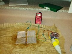
...and then I stuck them down with superglue and thermal paste. 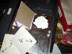
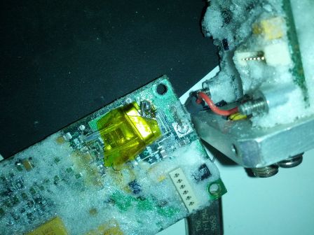
Not thinking to test the resistance first, I wired the whole thing up to
12VAC and it caught fire. In hindsight, this was a shit idea. Clearly the
conformal coating had failed at the solder points and short-circuited the whole
thing. Armed with a bottle of nail varnish remover, a screwdriver and a
scourer, I set about removing the boards and cleaning up the plate. I removed
the vias from the PCBs and glued them back on, this time component side to the
plate. I'd initially wanted to avoid doing this because of the thermal
resistance of the PCB, but it seems I have no other option. Here's the end
result: 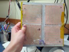 I still need to mount the thermistor
(probably with milliput) and wire up the PCBs. I need to buy some silicone wire
first for this.
And the other side of the heatbed, covered in kapton tape. There are a lot
of air bubbles although I tried my best to avoid them. In any case, I'm not
sure how this affects the print quality. 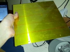
So that's my progress to date. I'll continue to post updates here.
Thursday 15 November 2012
Some Thoughts on Entropy and Energy
By alecjw on Thursday 15 November 2012, 01:15
In thermodynamics, we consider two related but substantially different properties of a system: energy and entropy. Both are hard to define - we might say that energy is "the ability to do work", but this isn't really true - consider a hot lump of metal. It certainly has energy, but the second law says we can't extract work from it without a colder reservoir. And even then we need to consider Carnot to tell us how much of this we can actually access. This definition applies better to exergy - the amount of energy available to do work, but let's not complicate things for now. When it comes to entropy though, we struggle even more to find a satisfactory description. Some would describe it as a measure of disorder, some tell us we don't need to define it in words - if we deal with it enough, we'll become comfortable with what it means.
But I find entropy troubling. Depressing, even.
Energy is a nice concept. Energy is always conserved - no matter what you do with it, it will always be there, just converted between its various forms. Entropy, on the other hand, via the second law, essentially states that in the fullness of time everything turns to shit. In everything we do, we make our energy less useful, everything a bit more samey and our toast a lot more burnt.
Entropy says you'll never get back out what you put in.
Entropy says you're on a one way street to a frozen demise.
Entropy says that one day everything you own will count for nothing.
Entropy says your first true love will never take you back.
Entropy says "things have changed, we have to move on".
Entropy says that you'll eventually die cold, unhappy and alone.
Entropy says there's no light at the end of the tunnel, because it's all fucked off into heat.
Entropy is the mistress of the universe - and a cruel mistress she is.
(This rant was adapted from a recent facebook status)
Saturday 27 October 2012
Microwave Modules MML 144/100 1/4
By alecjw on Saturday 27 October 2012, 22:01
I picked up this thing at a radio rally (Dunstable Downs) a while back for
£40. I wasn't really sure what I was buying, but I figured £40 for a 144MHz
100W linear isn't bad at all. 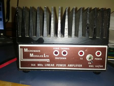
I've done a little bit of digging around and haven't been able to find out much about this specific model. It seems to be a rare early version of this. The reviews I've found seem to indicate that my version is by far the preferred one, since the newer one catches fire when running at high duty cycle, as you might guess from the smaller heatsink.
When I got it, the power cord went in through a hole in the back straight
onto the PCB with no grommet or strain relief. (No pictures, sorry.) I didn't
like that so I desoldered it, drilled out the hole to 12mm and added a strain
relief. It could perhaps have done with being a little bit bigger, since the
heavy gague wires were a nightmare to fit through it, but I managed in the end.
Here you can see my results: 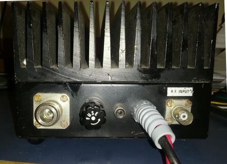 You'll
also notice here that the input and output connectors are BNC and N-type
respectively. The datasheet for the new model says that both should be SO259. I
wonder if these were replaced by the last owner (G8UBJ) or if this was part of
the original design? If it is a modification, I must say it's been done very
professionally.
Here's a shot of the inside. You can see where the previous owner replaced a
capacitor, which by the looks of the burnt remains on the PCB must have failed
quite catastrophically. Theres also a 470pf cap I replaced by myself because i
was clumsy and managed to shatter the old one. 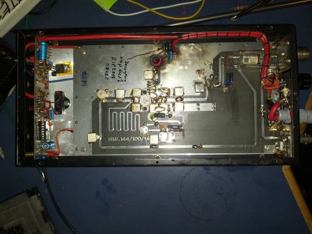
It looks quite well built to me, and I expect it will last a good few years to come. I've tested it with a 10W rig and it seems to put out something in the order of 100W, although I don't have the equipment to make precise power measurements. One thing I don't like is the case being held together with self-tappers. Some of the threads are already knackered. Once my reprap's working I plan to print out some enclosures for M3 nuts so I can bolt it together, unless anyone can suggest more eloquant solutions.
Wednesday 24 October 2012
Culinary Engineering #1: Greengage jam
By alecjw on Wednesday 24 October 2012, 23:38
I went into the kitchen this evening to find this:  Free greengages! I have no idea what
a greengage is, but I remember it's something you make jam with. So I looked up
a recipe, and found that Jamie Oliver recommends 1 part sugar to 2 parts
greengages (by mass). And some other crap too, but we can forego that. I didn't
have any scales, but luckily I did have a steel rod lying around... I marked
out a position about 2/3 of the way along, put a rubber band around it to hang
it from, then tried as best i could to balance the greengages on the short arm
with the sugar on the long arm. I cut the greengages and plums in half and left
them to simmer in the sugar.
The recipe suggested that the stones should float to the top. They didn't and I had to separate them out manually with a wooden spoon (if I'd known, I'd have taken them out beforehand...)
Either way though, the final result was delicious! I just had some on
toast... omnomnomnomnom 
Monday 22 October 2012
Reprap Build: Phase 2
By alecjw on Monday 22 October 2012, 16:53
A wild reprap update appears! Sorry for the delay, I suck.
So, I've been back at college for a while now, and I arrived to find my
pigeonhole filled with little slips saying I had 15 parcels! Amongst these were
the stepper motors: 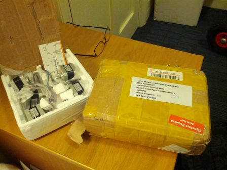 (You can see here my postal address
if you want to send me spam)
And the sanguinololu board and parts (Here pictured after my dreadful
attempt at soldering it): 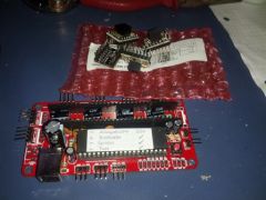
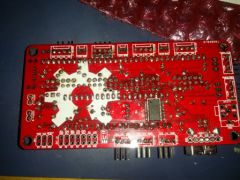
Plus a load of boring nuts, bolts, washers, bearings....
Beyond having gotten hold of most of the parts, I'm afraid that owing to
being busy with work, I haven't much more to report. I have however made a
start on the frame! 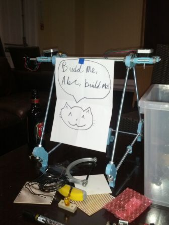 This picture was taken at the RepRap
meeting I organised at Homerton college bar. Techmeology was there and planned to build a
3D printer out of old flatbed scanners, whilst George Newson (seemingly no
internet presence to link to here) plans to build a 3D printer for steel.
If you know anyone else from Cambridge who might be interested in 3D printing, point them my way - I'd like to organise another meeting and potentially start a university RRUG. And if you're interested yourself, let me know on aw570 or me at this domain.
That's all for now!
Sunday 23 September 2012
Halfords Inverter Failrepair
By alecjw on Sunday 23 September 2012, 04:18
Just a quick one for this morning... My experiences with an in-car inverter, along with a bit of a rant. (edit: having finished writing this it's turned out not to be quite as short as I expected. Sorry!)
I bought one of these broken off ebay a while back for 99p - I figured I'd replace the output transistors on the H-bridge and everything would be fine. It arrived and I opened it up - what I saw was utterly horrific. The inverter circuitry was just a 556 circuit and was about 15Hz (30%!) out of callibration. The DC-DC converter is completely open loop: at 15V input (within spec!) it will put out around 400V. There is an optoisolator but it doesn't seem to do anything most of the time, although shorting the output switched the thing off so I think it has something to do with the thermal cutout. The inverter circuitry has a few more ICs alongside the 556 timer which I'm guessing provide some sort of crude RMS voltage regulation by varying the pulse width but quite frankly I can't be fucked to try and work it out because clearly someone couldnt be fucked to design this thing properly and I'm just plain fed up of it by this point. On top of this, the mechanical design was shoddy - the PCB was held in place by the transistors. I cannot stress strongly enough - do not buy one of these. I'm not sure if these design flaws are common to all in-car inverters but they're certainly widespread. If you do need an in-car inverter, I don't know what to suggest. Build your own, I suppose... sorry. Or if you must buy a cheap one, be aware of their limitations.
Anyway, here's what I did with mine: after I was unsucessful in fixing the
problem by replacing the H-bridge transistors, I couldn't be bothered to do any
more faultfinding and decided to demote it from inverter to DC-DC converter. It
would quite happily put out ~300VDC, so I figured this would be fine for
anything with a switch mode power supply. I removed the H-bridge transistors
and soldered the live and neutral lines to the +ve and -ve rails. Here you can
see the top of the PCB where i've removed the transistors and the underside of
the board where I've soldered the cables to the rails: 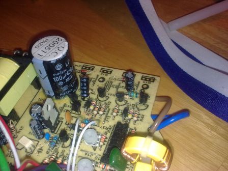
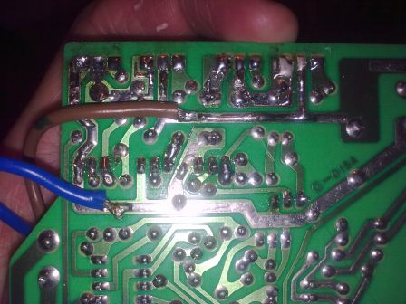 (in the second image, you can
also see where I cauterised my finger by touching the 300V rail)
I plugged my laptop charger in and hoped for the best, being ready to catch the magic smoke if need be. All went well and I'm now writing this with my laptop charging from this inverter. It won't be good for much else since DC is no good for line frequency transformers or voltage doubler circuits, but I'm happy that I have something I can use my laptop with in the car. Yeah, a bit of a cop out option - I could probably have fixed it if I could be bothered but I deemed it not to be worth the effort. It works with my laptop charger anyway so that's all that's I care about.
I scrawled a warning on the top just in case this deathtrap finds itself in
someone else's hands. I derped a bit writing the date: 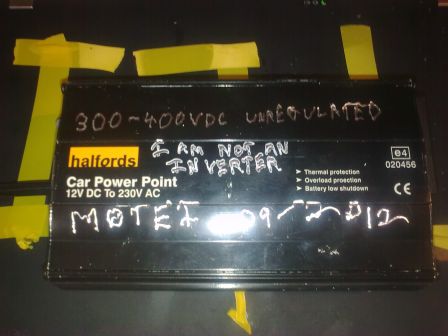
Wednesday 19 September 2012
Reprap Build: Phase 1 - Addendum
By alecjw on Wednesday 19 September 2012, 11:58
For more info check out the reprap website.
Tuesday 18 September 2012
Reprap Build: Phase 1
By alecjw on Tuesday 18 September 2012, 23:55
Ohai, first post and all that. Whatever.
I've been looking into building a reprap lately, mostly just because it would be awesum to have one on my desk, but also because there have been plenty of situations when i've thought, "I wish i had a reprap right now..." I decided on the Prusa mendel iteration 1, because i was told that there are a few problems to be ironed out with iteration 2.
The printed parts were loaned to me by Glen Searle, who runs a 3d printing
business. I would tell you to check out his website but it seems to be down at the
moment. How do you loan parts though? Surely i need to build them into my own
printer? Well the answer is I build mine, print out a new set of parts and give
them back to him. I also bought an extruder hot end off him for £50 - he threw
in some threaded rod too. 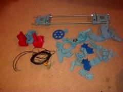 (edit: Glen has asked me to add that
the non-sky-blue parts were printed while we sat there eating pizza. And good
pizza it was too.)
I've also ordered a couple of other non-printed parts: I got some stepper motors and linear bearings from aliexpress (essentially like ebay but cheaper and more chinese) and I'm basically going to get the rest of the mechanical parts from screwfix/ebay. I'll post links for my complete bill of materials when I'm done, but for now I don't want to be making recommendations before I'm sure I haven't been ripped off myself.
Today I was at the hackspace working on the heatbed for my reprap. I have a
load of 160x100mm photo etch PCBs, so i figured I could do something with that
- cut them down to squares and tesselate four together to make my 200x200mm
heater bed. I'm not yet sure how i'll fix them together but we'll cross that
bridge when we get there... Anyway, I decided on a zig-zag patten of parallel
tracks, 2mm apart and d wide. I did some calculations to find d based on the
fact that a typical heater bed resistance is 2 ohms (so I aimed for 0.5 ohm per
board) and the copper will be 35 microns thick. As you can see from my
calculations below, I ended up with a track width of 2.28mm. If enough people
hassle me for it, I might write a script to automatically do these calculations
and spit out an SVG file. Although this time round I was lazy and made the
design in libreoffice. PDF is
here. 
I etched these boards at the hackspace today using cheap (not FR4) board,
and here's the result: 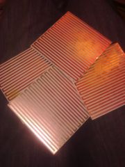
First impressions were these seemed to have been a success. I measured the
resistance of one with a multimeter and it came out as 0.5 ohms. I then hooked
them up to a few linear power supplies and found that they didnt actually get
that hot: with 9 amps flowing through them, they were still less than 100
degrees. At 7 amps, they seemed to be about an ohm each. Not to worry though,
nothing which can't be solved by MOAR VOLTZ: I'll just wire them up
differently: either 12V straight across one or 20v in series parallel. That's
all for now, I'll document all further progress here. But first I'll leave you
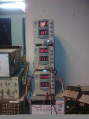
with a picture of my test setup: for those times when two linear PSUs stacked
on top of each other just don't cut it... 